
Pointing Budgets and Stabilization Loops: Control Architecture for SOTM Antenna Positioners
How to divide a ±0.32° pointing budget across alignment, gyro drift, servo lag and structure flex - and how to choose between MEMS rate loops, FOG-based inertial stabilization and cascaded beacon-trim architectures for SOTM antenna pedestals.
1. Where the pointing budget goes
Start from the beam. A 45 cm antenna at 30 GHz has a half-power beamwidth of roughly 70 lambda / D, i.e. about 1.56°. For a Gaussian main lobe, pointing loss is approximately L = 12 x (theta / theta3dB)^2 dB, so a 0.5 dB link margin reserved for misalignment allows only about ±0.32° of total pointing error. Everything the platform does must fit inside that window - on both axes, all the time, while the vehicle moves.
| Error contributor | Typical magnitude | Mitigation |
|---|---|---|
| Boresight alignment after installation | 0.1-0.3° | One-time calibration against beacon or known satellite |
| Gyro bias drift (uncorrected tactical MEMS) | 1-10°/h | Bias estimation at startup plus slow beacon-trim correction |
| Servo lag under carrier disturbance | 0.05-0.15° RMS | Stabilization loop bandwidth 5-10x the dominant disturbance frequencies |
| Structure flex and mount resonance | 0.05-0.15° | Stiffer pedestal, resonance identified and notch-filtered |
The practical takeaway: alignment and flex consume most of a tight budget before the servo loop even moves. That is why pedestal geometry and stiffness are control problems, not just mechanical ones.
2. Choosing the stabilization architecture
Three architectures dominate SOTM terminals. They differ in how disturbance rejection is achieved and what they demand from the inertial sensors.
| Architecture | Disturbance rejection | Sensor requirement | Typical residual jitter |
|---|---|---|---|
| Wide-bandwidth rate loop (gain stabilization) | Strong up to loop bandwidth (25-50 Hz) | Tactical MEMS gyro, low noise over low bias | 0.1-0.2° RMS (land/maritime) |
| Inertially stabilized (FOG-based) | Very strong, DC-coupled | Fiber-optic gyro, bias below 0.1°/h | 0.02-0.05° RMS |
| Cascaded: gyro loop + slow beacon/step-track trim | Gyro loop handles dynamics, trim loop removes bias | MEMS + RF beacon or spectrum detector | Approaches inertial case at low cost |
For land and maritime platforms, the dominant carrier disturbance sits between 0.1 and 5 Hz (sea-state roll reaches ±20° or more at 0.1-0.5 Hz), which is exactly the band a 25-50 Hz rate loop covers well. The cascaded architecture is therefore the default choice for SWaP-constrained commercial terminals: a MEMS-based rate loop rejects the dynamics, while a 1-2 Hz tracking loop slowly removes whatever bias and alignment error remains. A FOG-based design is reserved for narrow-beam (0.5° class or tighter) or high-value military links where the 0.02° residual justifies the sensor cost.
3. Sizing the axes and picking the drive
Each axis must deliver T = J x alpha + T_friction + T_disturbance. Worked example for a 25 kg stabilized platform with gimbal inertia of 1.8 kg·m² and a worst-case slew of 60°/s at 120°/s²: the inertial term is 1.8 x 2.09 = 3.8 N·m, seal and bearing friction adds 1-1.5 N·m, and wind loading on the dish in a 60 km/h gust adds another 2-3 N·m. Peak demand lands around 7 N·m, which a 400-750 W motor with 3x overload covers comfortably - the overload, not the nameplate power, is what actually closes the case.
| Drive train option | Backlash | Pointing accuracy | Best fit |
|---|---|---|---|
| Worm or spur gearbox | 0.1-0.5° | Limited by backlash | Cost-driven, coarse-beam terminals |
| Harmonic/cycloidal reducer | 0.05° or less | Good, with stiff coupling | Compact two-axis gimbals |
| Direct drive (hollow shaft) | None | ±0.01° class | Continuous-rotation azimuth, slip-ring integration |
Direct drive wins the azimuth axis whenever the terminal must rotate continuously to track LEO passes or integrate a slip ring - there is no backlash to inject limit-cycle jitter into the gyro loop. For roll/pitch stabilization of the antenna itself, a dedicated two-axis platform keeps the mechanics simple and lets the drive electronics live below deck.
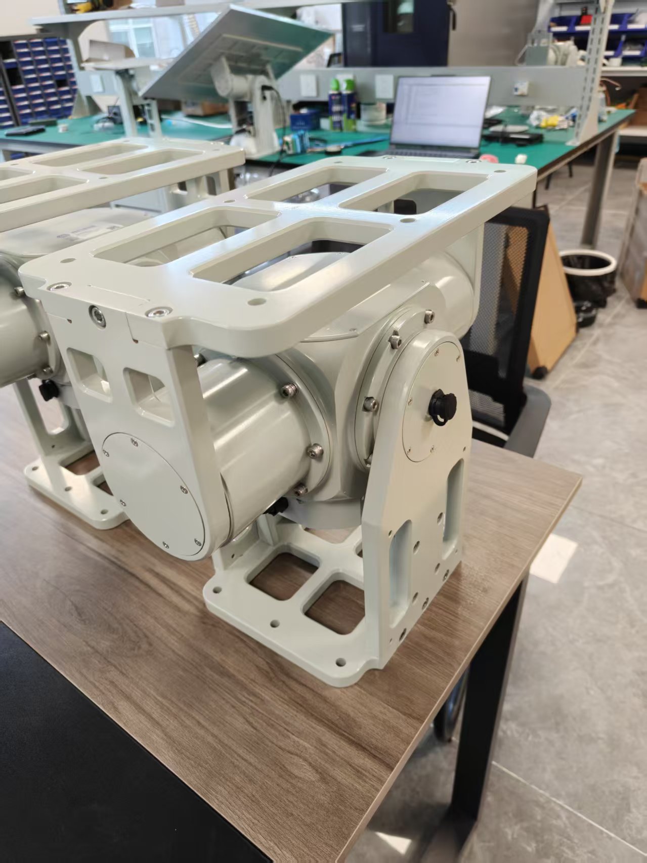
Repunite building blocks for this class of terminal: the RU-STP-25-080 shipborne stabilized platform (25 kg payload, roll/pitch disturbance compensation, flat-panel compatible), the RU-SF-D48-40 direct-drive azimuth turntable (±0.01°, integrated slip ring, unlimited rotation), and the JGDSD 3kW 48V MIL-grade drive (3x overload, -40 to +85 °C, CANopen) - plus the M2 80 mm 750 W servo motor with 23-bit absolute encoder for auxiliary axes.
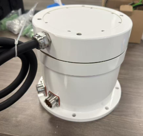
Single-Axis Azimuth Servo Turntable 40 · Direct Drive
Hollow-shaft direct drive, zero backlash, ±0.01° accuracy, built-in slip ring, 40kg load
View details →
Shipborne SATCOM Stabilized Platform 25KG
Roll/pitch disturbance compensation, flat-panel antenna compatible, lightweight
View details →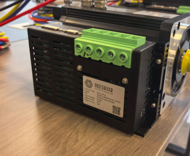
JGDSD 3kW 48V MIL-Grade Servo Drive
3x overload, -40 to +85 °C, CANopen/RS485, vibration and shock tolerant
View details →