
Slip Rings, Cable Wraps and Rotary Joints: Power and Signal Transfer in Continuously Rotating Turntables
How to choose and size the rotating interface on an azimuth turntable: cable wrap vs capsule and through-bore slip rings vs fibre and RF rotary joints, with worked voltage-drop and loss numbers for a 48 V 3 kW axis and signal budgets for encoders, Ethernet and video.
1. Start from the duty cycle, not the datasheet
Two numbers decide which interface is viable: how many turns of travel the axis needs, and how many revolutions it will accumulate over life. A pan axis that swings +/-180 degrees is a cable-wrap problem. An axis that must keep turning - continuous-scan radar, SOTM terminals re-acquiring a LEO pass, a slip-ring-fed inspection head - is a slip-ring problem.
The arithmetic is unforgiving. A torsional cable routed around a 60 mm bundle path consumes about 0.94 m of cable to store five turns, before the service loop, and each revolution twists the conductor roughly 150 degrees per metre. At a typical 30 deg/s slew rate one revolution takes 12 s, so 10 million revolutions is 3.8 years of continuous operation and 50 million is 19 years. Ordinary flexible cable does not survive that in torsion; a torsion-rated cable rated for 1-2 million cycles at +/-150 deg/m does not either.
| Interface | Rotation | Power per circuit | Data | Typical life | Where it fits |
|---|---|---|---|---|---|
| Cable wrap (torsion-rated) | +/-3 to 5 turns | 48 V, a few A | Low-rate signals only | 0.5-2 million cycles | Limited-travel pan/tilt, cost-sensitive |
| Capsule slip ring | Unlimited | 2-5 A, 6-12 circuits | Ethernet only in rated variants | 10-50 million rev | Compact azimuth axes, 1-3 kW |
| Through-bore slip ring | Unlimited | 10-15 A, 24-36 circuits | 1GbE optional, fibre option | 20-100 million rev | Hollow-shaft direct-drive turntables |
| Fibre optic rotary joint (FORJ) | Unlimited | None | 1-10 Gbps | >100 million rev | HD video, 10GbE uplink |
| Coax / RF rotary joint | Unlimited | None | DC-18 GHz | >10 million rev | Antenna RF path, 0.3-1.0 dB insertion loss |
Note what the table implies: a single joint rarely does everything. High-current power, low-level encoder signals, gigabit Ethernet and an RF channel normally need two or three different interfaces stacked on the same axis - which is the real reason hollow-shaft turntables are built around a large bore.
2. Sizing the power path: current, contact resistance, voltage drop
A 48 V, 3 kW azimuth drive draws 62.5 A. At a contact resistance of 10 mOhm per circuit that is 0.63 V of drop, 1.3% of the bus, and 39 W dissipated inside the joint - enough to derate the ring, heat the housing and cook the adjacent signal circuits. Splitting the feed across two circuits halves the loss to 19.5 W; four circuits bring it to 9.8 W and keep the ring well inside its thermal envelope.
| Configuration | Current | Contact R | Voltage drop | Loss in joint |
|---|---|---|---|---|
| 1 x 62.5 A | 62.5 A | 10 mOhm | 0.625 V (1.3%) | 39.1 W |
| 1 x 62.5 A, premium ring | 62.5 A | 5 mOhm | 0.312 V (0.65%) | 19.5 W |
| 2 parallel circuits | 31.25 A each | 10 mOhm | 0.312 V | 19.5 W total |
| 4 parallel circuits | 15.6 A each | 10 mOhm | 0.156 V | 9.8 W total |
| Cable check: 3 m, 0.75 mm2, 5 A | 5 A | 0.070 Ohm | 0.35 V | 1.75 W |
| Cable check: 2 m, 16 mm2, 62.5 A | 62.5 A | 0.0022 Ohm | 0.137 V | 8.6 W |
Use R = rho x L / A with rho = 0.0175 Ohm mm2/m for copper at 20 C, and add roughly 0.4% per degree C for a housing that sits in the sun. Then apply the derating the ring vendor publishes for ambient temperature and speed: a ring rated 10 A per circuit at 20 C is often 6-7 A at 60 C in still air. Design to the derated number, not the headline one.
Put the product numbers next to that arithmetic. The 40 kg class azimuth turntable carries an integrated ring rated 30 A of power, six signal channels and two 100 Mbit Ethernet ports; its 1.5 kW axis draws about 31 A at 48 V, which is right at the single-circuit limit and is why a 3 kW requirement is a two- or four-circuit design rather than a bigger contact. Budget the drop against what the load actually needs. A 48 V bus tolerating 1% has 0.48 V to spend; a 24 V brake or heater circuit has 0.24 V. That is why the power circuits get the large conductors and the big contacts, while logic-level supplies should never share a ring with a 60 A motor feed.
3. Signals: what the ring does to an encoder and to Ethernet
Contact resistance on a brushed ring fluctuates by roughly 10-30 mOhm as it turns. On a 48 V power rail that is invisible. On a low-level differential encoder line it appears as timing jitter, and on a high-speed serial link it appears as retransmits and dropped packets. Three rules cover most of it.
Keep feedback on the motor side where possible. A hollow-shaft direct drive with an encoder on the motor rotor never has to cross the rotating interface. Add a load-side encoder only when the application needs output-side accuracy through backlash or structural wind-up, and then give it its own low-noise signal circuits with separate returns.
Never run copper Ethernet through a general-purpose power ring. 1000BASE-T needs a controlled 100 Ohm differential impedance end to end; a random pair through a power ring has neither the impedance control nor the crosstalk rejection, and the link will negotiate down or drop under vibration. Use an Ethernet-rated ring (specified impedance and bit-error rate) or a fibre optic rotary joint, and keep the copper only for the low-rate service channel.
| Signal | What it needs | Recommended path | Budget to hold |
|---|---|---|---|
| Incremental encoder, RS-422 | Shielded twisted pairs, stable contact resistance | Dedicated signal ring, separate return per pair | Position jitter <0.01 deg |
| Absolute encoder, BiSS-C | 10 MHz clock, controlled termination | Dedicated signal ring, pigtails under 0.5 m | <30% timing margin consumed |
| 1000BASE-T | 100 Ohm +/-10%, Cat5e or better | Ethernet-rated ring or FORJ | <1% retransmit rate |
| 3G-SDI video | 75 Ohm, 1.5 Gbps | FORJ with single-mode option | Insertion loss <2 dB |
| RF Tx/Rx, Ku-band | VSWR <1.5, phase stability | Coax rotary joint, one channel per band | 0.3-1.0 dB insertion loss |
Grounding deserves its own line in the interface document. Carry the shield through dedicated shield circuits rather than tying it to the ring body, ground at one end for low-frequency signals, and bond the turntable housing to the pedestal with a low-inductance strap so that motor return current does not travel through the signal returns.
4. Mechanical integration and life
Three mechanical choices constrain the electrical one. First, bore size: a through-bore ring is what allows a hollow-shaft direct drive to stay short axially while the customer's harness passes straight through, so specify the bore from the largest connector that must transit, not from the motor. Second, sealing: outdoor pedestals need IP65 or better at the rotating interface, plus salt-spray-rated housings for coastal sites, and the ring cavity must be sealed off from the encoder cavity - brush dust is conductive and will find its way into an optical disc. Third, service access: ask for a life curve at your operating speed and current rather than a single revolution figure, because brush wear scales with both, and set the service interval to match the site visit schedule the customer will actually keep.
For RF on the axis, budget the channels early. Each waveguide or coax rotary joint adds insertion loss, a VSWR contribution and mechanical length; combining Tx and Rx on one joint with a diplexer is often better than stacking two joints, provided the diplexer's isolation meets the link plan.
5. Selection summary for 20-40 kg azimuth turntables
For a continuously rotating antenna or sensor axis in the 1-3 kW class, the pragmatic default is a through-bore slip ring integrated under a hollow-shaft direct drive: power split across two or four circuits, encoder feedback on the motor side, Ethernet on a rated ring or fibre, and RF on a dedicated coax rotary joint. Cable wrap stays attractive only where travel is genuinely limited to a few turns and the axis is cost-sensitive; it is not a shortcut for a continuous-scan axis.
Repunite's RU-SF-D48 series azimuth servo turntables apply exactly this architecture: hollow-shaft direct drive with zero backlash, a rated 1.5 kW hollow-shaft motor, +/-0.01 degree positioning accuracy on the 40 kg class (0.1 degree on the 20 kg class), and an integrated slip ring - 30 A of power, six signal channels and two 100 Mbit Ethernet ports - for unlimited continuous rotation, driven by MIL-grade 48 V servo drives rated for 3x overload and -40 degree C cold start. If you are sizing a rotating interface and want a second opinion on the power and signal budget, send the duty cycle and we will run the numbers with you.

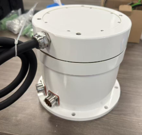
Single-Axis Azimuth Servo Turntable 40 - Direct Drive
1.5 kW hollow-shaft direct drive, zero backlash, +/-0.01 deg accuracy, slip ring 30 A / 6 signal / 2x100M Ethernet, 40 kg load
View details →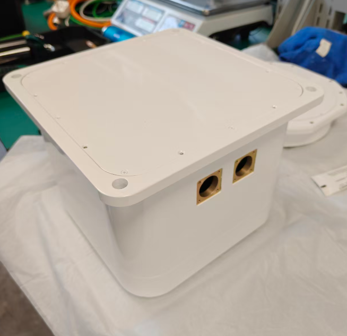
Single-Axis Azimuth Servo Turntable 20 - Direct Drive
Compact 20 kg class, +/-0.1 deg accuracy, slip-ring continuous rotation, low profile for UAV and vehicle mounts
View details →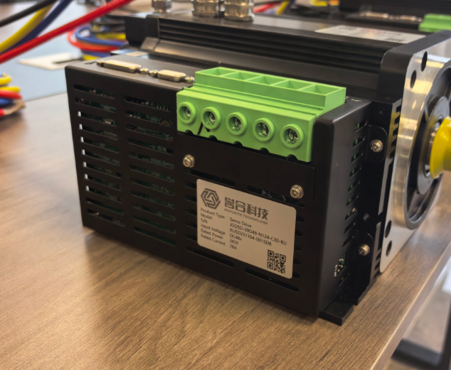
JGDSD 3kW 48V MIL-Grade Servo Drive
3x overload, -40 to +85 deg C, CANopen/RS485, vibration and shock tolerant
View details →