
Specifying Servo Turntables for LEO Tracking Antennas: Torque, Acceleration and Tracking Accuracy
LEO constellations have changed the duty cycle of ground-segment positioners. This guide walks through the four calculations that matter when specifying a two-axis servo turntable for LEO tracking: peak tracking rate, torque budget, acceleration headroom and pointing accuracy allocation.
The shift from GEO to LEO has quietly rewritten the specification sheet for ground-station positioners. A GEO earth station may spend its whole life holding a single pointing vector with occasional tracking corrections. A LEO gateway antenna, by contrast, slews through a pass lasting only minutes, resetting between passes, thousands of times per year. The servo turntable underneath that antenna is no longer a static pedestal — it is a precision motion system, and specifying one deserves the same rigor as specifying the RF chain.
Below are the four calculations and design checks that matter most when selecting a two-axis servo turntable for LEO tracking antennas, based on parameters from our own PTU product line and typical 3–5 m gateway-class apertures.
1. Peak Tracking Rate and Angular Acceleration
Start from geometry. For a LEO satellite at altitude h observed from the ground, the maximum angular rate seen by the antenna occurs near zenith and can be estimated as:
ωmax ≈ vorb / hslant,min
For a 550 km constellation (vorb ≈ 7.6 km/s) tracked down to 10° elevation, slant range at closest approach is roughly 1,100 km, giving a peak rate of about 0.4°/s near zenith. Add margin for acquisition slews, handover re-acquisitions and fast repositioning between passes, and a practical specification is a continuous slew rate of 10–30°/s and a tracking rate of 1–5°/s with smooth velocity loops at 0.1°/s and below.
The often-overlooked number is angular acceleration. Pass handovers and off-axis re-acquisition demand 50–200°/s² without losing encoder lock. A turntable gearbox that cannot deliver this acceleration converts every handover into a reacquisition delay — directly reducing daily contact time.
2. Torque Budget: More Than Wind Loading
A common specification error is sizing the drive from steady-state wind torque alone. The full torque budget for each axis includes:
| Component | Typical share | Notes |
|---|---|---|
| Unbalance & gravity torque (elevation axis) | 20–40% | Minimized by careful antenna/counterweight placement on the azimuth axis |
| Wind torque (stow survival vs. operational) | 30–50% | Operational wind is the design case; stow mode uses a separate brake |
| Acceleration torque (J·α) | 15–30% | Dominated by antenna inertia reflected through the gearbox ratio |
| Friction & seal drag | 5–10% | Grows with slew-ring wear; leave 20% life margin |
For a 4 m class antenna at 60 m/s survival wind, peak stow torque can reach several kNm, while operational tracking torque may be one order of magnitude lower. This wide dynamic range is why we favor servo motors with field-weakening headroom plus a failsafe brake — the motor is sized for operational torque and acceleration, while the brake carries stow loads. Our shipborne SATCOM stabilization platform follows exactly this architecture: position control plus disturbance compensation on the roll and pitch axes, with continuous status monitoring and safety protection built in.
3. Pointing Accuracy Allocation
Link budgets typically tolerate 0.2–0.5 dB of pointing loss. For a 4 m Ka-band antenna (beamwidth ≈ 0.45°), that allows roughly 0.1–0.15° RMS total pointing error. Allocate it before you select hardware:
- Structural & alignment: 0.03–0.05° (boresight calibration, pedestal leveling)
- Servo tracking error: 0.03–0.05° (wind disturbance rejection, friction, backlash)
- Sensor & ephemeris error: 0.02–0.05° (beacon tracking, GNSS/INS aiding, TLE age)
The servo share is bought with feedback resolution and loop bandwidth: absolute encoders on both axes (17-bit or better on the output), backlash under 1 arcmin at the output, and a velocity loop bandwidth high enough that wind gusts appear as a DC offset rather than a disturbance. Open-loop step-and-settle schemes cannot meet this allocation under dynamic wind loading.
4. Duty Cycle, Environment and Lifecycle
A LEO gateway positioner moves constantly — a duty profile closer to a machine tool than a traditional antenna mount. Check three things: gearbox duty rating (continuous S1 vs. intermittent), bearing life under slewing loads (slew rings are the wear item, not the motor), and environmental sealing to at least IP65 for outdoor pedestals, with operating temperature ranges covering the site climate. For mobile and maritime variants, inertial stabilization replaces the fixed-horizon assumption entirely, which is why our SOTM pan-tilt integrates dual Beidou B1/GPS positioning and inertial-navigation tracking to hold pointing while the carrier itself moves.
Recommended Repunite Products

SOTM Pan-Tilt System
Beacon-guided acquisition and tracking with INS aiding; azimuth/elevation circular, sector and conical scanning for vehicle- and ship-borne SATCOM.
View details →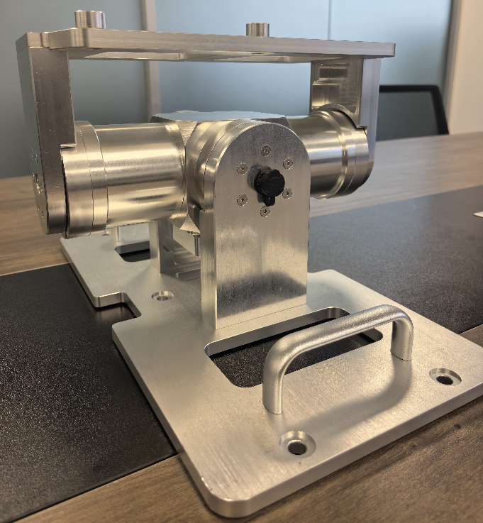
Shipborne SATCOM Stabilization Platform
Two-axis roll/pitch stabilization with disturbance compensation; lightweight turntable compatible with flat-panel antennas.
View details →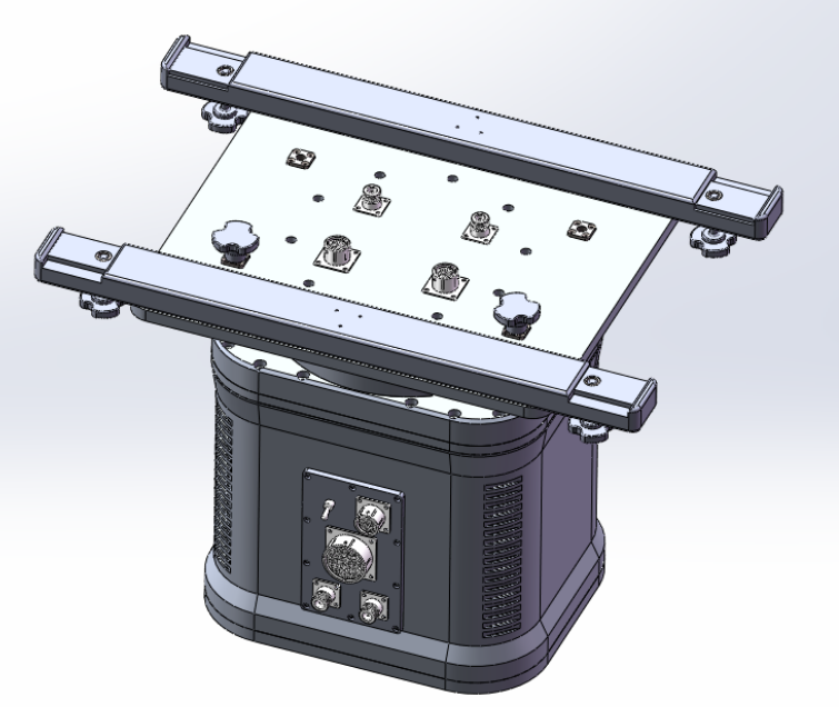
PTU-S80 Heavy-Duty Pan-Tilt
High-payload two-axis positioner for radar and optical payloads with real-time status monitoring and safety protection.
View details →If you are planning a LEO tracking station, a SOTM retrofit, or a stabilized platform for a moving carrier, our engineering team can run the torque and accuracy budget with your antenna parameters. Contact Repunite to discuss your pointing requirements.