
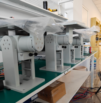
Sizing Antenna Pedestals for Polar and Low-Elevation SATCOM Tracking
Arctic maritime constellation programs are moving from feasibility to procurement. What changes in pedestal sizing when elevation drops below 10 degrees, handovers arrive every 10 minutes, and deck temperature swings 60 degrees — plus a practical three-number selection workflow.
Why Low-Elevation Tracking Breaks Conventional Pedestal Sizing
Most stabilized antenna pedestals are sized for mid-latitude GEO links, where elevation angles stay between 20 and 60 degrees and azimuth torque demand is modest. Polar routes break both assumptions at once. A vessel sailing the Northern Sea Route or transiting between the Atlantic and Pacific via the Arctic sees GEO satellites at elevations below 10 degrees — often below 5 — which multiplies the lever arm between the antenna's center of gravity and the pedestal bearings, and pushes peak slew torque during turn maneuvers far above the cruise-state value.
When constellation operators move services to highly elliptical or polar low-earth orbits, as the emerging Arctic maritime programs do, the tracking problem compounds: satellites cross the horizon quickly, handovers are frequent, and the pedestal must slew through large angles at consistent angular rates. A pedestal selected with only a GEO boresight in mind will run out of torque margin exactly when the link is hardest to hold.
| Parameter | Mid-latitude GEO tracking | Polar / low-elevation tracking | Design consequence |
|---|---|---|---|
| Typical elevation angle | 20-60° | 5-15° | Larger gravity moment arm on elevation axis |
| Peak slew demand | ≤10°/s | 30-60°/s during handover | Servo drive sizing must use peak, not cruise, torque |
| Handover frequency | None (fixed arc) | Every 8-15 min (LEO) | High-duty slewing raises thermal load on motors |
| Vessel motion input | Roll ±15°, period 6-10 s | Same, plus ice-induced shock | Peak torque reserve ≥2.5× continuous rating |
Torque, Bandwidth and Thermal Budget: The Three Numbers That Matter
A practical selection workflow needs only three computed numbers before comparing products. First, peak torque: combine the antenna's mass moment of inertia with the worst-case angular acceleration from vessel motion plus handover slew. For a 0.6-1.0 m maritime antenna, this typically lands between 15 and 40 N·m at the elevation axis — well above what a small instrument-grade PTU delivers, and the reason true maritime pedestals use framed two-axis structures with hollow-bore rotary joints.
Second, servo bandwidth: the stabilization loop must reject roll and pitch disturbance entering at 0.1-0.3 Hz (typical swell periods of 3-10 s) with at least 20 dB of attenuation. That calls for a current-loop bandwidth in the kilohertz class and a velocity loop above 50 Hz — specifications that modern digital servo drives meet comfortably but that set a hard floor on encoder resolution (17-bit class or better on both axes).
Third, thermal budget: LEO handover profiles convert the duty cycle from intermittent to near-continuous slewing. Continuous torque rating, not peak, determines whether the motor survives a 12-hour passage. Verify that the vendor's continuous rating is specified at the actual ambient — Arctic deck installations routinely see -25°C to +40°C, and motor thermal models quoted at 25°C laboratory ambient flatter reality by 20-30%.
| Spec item | Minimum for polar maritime SATCOM | Repunite PTU-Shipborne class |
|---|---|---|
| Azimuth continuous torque | ≥20 N·m | Framed 2-axis, hollow-bore design |
| Slew rate | ≥45°/s azimuth | ≥60°/s |
| Positioning accuracy | ≤0.1° | ≤0.05° with 17-bit encoders |
| Stabilization isolation | ≥30 dB @ 0.1-0.3 Hz | Closed-loop IMU-coupled servo |
| Operating temperature | -25°C to +55°C | Industrial-grade rated |
| Ingress protection | IP66 deck-mounted | IP66 available |
From Study to Deck: What Buyers Should Ask Vendors Now
The GomSpace-led study is a reminder that polar maritime connectivity is moving from concept to procurement within this budget cycle. Ground-segment buyers preparing requirements for Arctic-capable terminals should demand motion-profile-specific data, not brochure numbers: peak and continuous torque at the mounted elevation angle, measured stabilization isolation against a 0.2 Hz disturbance input, and documented performance after thermal soak at -25°C.
It is also worth specifying how the pedestal integrates with the terminal's modem and IMU. A pedestal that exposes a standard EtherCAT/CANopen servo interface and accepts external stabilization references will integrate into both GEO legacy links and LEO tracking chains, protecting the investment as the constellation layer evolves.
Repunite's stabilized platform family — including the PTU-Shipborne SATCOM pedestal and framed 2-axis units — is engineered around exactly these requirements: high-torque framed axes, 17-bit feedback, hollow-bore cable routing, and servo drives with bandwidth headroom for LEO handover duty. Contact us for sizing worksheets matched to your antenna aperture and route profile.
Recommended Repunite Products
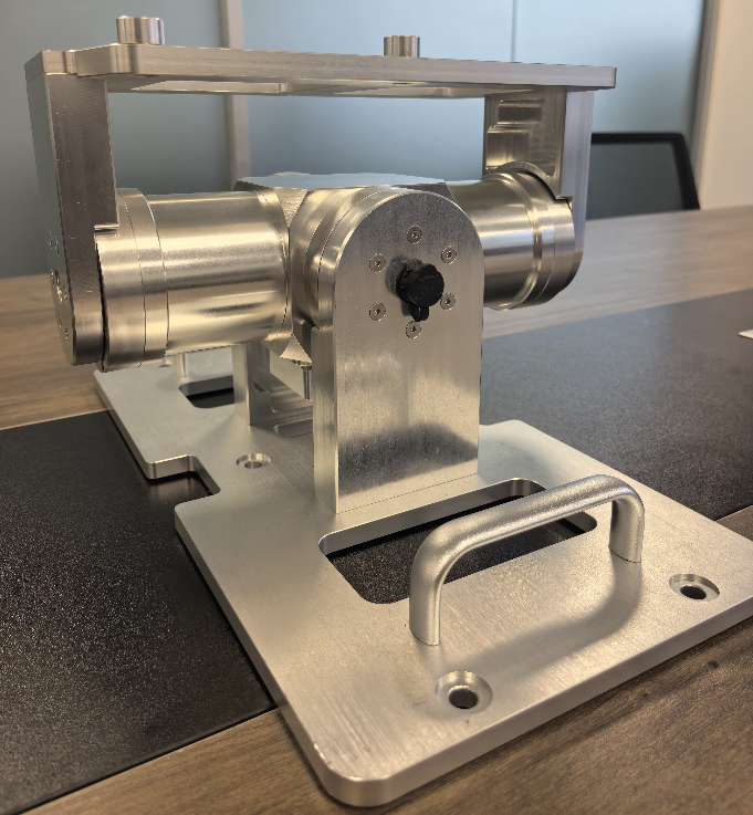
PTU-Shipborne SATCOM Pedestal
Two-axis stabilized pedestal for maritime SATCOM with disturbance compensation.
View details →
Framed 2-Axis Stabilized Platform STP-130-035
Framed two-axis positioner with hollow-bore routing for antenna payloads.
View details →
SOTM Pan-Tilt System
Beacon-guided tracking with INS aiding for vehicle- and ship-borne SATCOM.
View details →